

Electro-Medical Devices are powered by the mains or an internal power source (batteries) and often attached to the patient by wires. Some of these devices have active parts inserted into the patient body and may come in direct contact with the heart. There is a risk to the patient in the event of current leaking from the device. Current can also be transmitted through a caregiver such as a nurse in contact with an electronic device near the patient. Electrical shock can cause disruptions during health care procedures and result in injury or death. This makes electrical safety a topic of very high importance in medical device quality assurance.
Physiological effects of electrical shock range from a tingling sensation to serious burns and electrocution. Excitable human tissue is very sensitive to current in the frequency range of electrical power systems worldwide (50 Hz to 60 Hz). The figure below shows the effects of current flowing from one skin contact point to another.
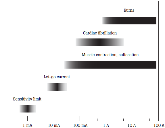
Electrical safety takes on added significance in electrically-susceptible patients. For cardiac procedures, electrically-conductive catheters may be placed into the heart while the patient is connected to medical equipment. This procedure puts patients at risk for ventricular fibrillation. Skin exhibits a high electrical resistance, but internal body components such as blood and muscle have a low electrical resistance. In fact, currents as low as 20 microamps have caused ventricular fibrillation in experiments conducted with dogs when a conductor made direct contact to the heart.
The term macroshock describes electrical current applied externally. On the other hand, the term microshock is used to describe direct shocks to the cardiac muscle. As a result of data collected regarding macroshock and microshock, worldwide standards have been established to limit leakage current.
In equipment designed for low resistance direct contact with patients, such as indwelling catheters, electrical isolation techniques are used to reduce the current flowing to the patient to minimal levels. In the event of a device failure or short-circuit condition, the patient is protected from microshock. These techniques may utilize isolation transformers and optical circuits. Thus, electrical safety standards specify low microampere limits for direct patient contact equipment.
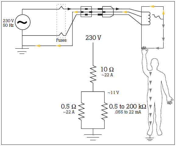
To reduce leakage current to negligible levels, chassis grounding is utilized to shunt any leakage or fault current to ground rather than to the patient or staff. Figure 1 demonstrates the hazard current from the electrical failure being safety shunted to ground through this alternative pathway. Effective grounding can only be achieved with very low resistance pathways to ground on the order of tenths of an ohm. Grounding is another measurement specified in electrical safety standards for medical devices.
To help verify the functionality and safety of medical devices, electrical safety standards have been established in the United States, European countries, and other parts of the world. The standards differ in criteria, measurements, and protocol.
The International Organization for Standardization (ISO) and the International Electro-technical Commission (IEC) organizations based in Europe provide standards worldwide in partnership with the World Trade Organization. These include standards for electro-medical equipment. There are general and specific standards for medical device electrical safety.
The primary standard for medical devices is IEC 60601. General requirements for protection against electric shock hazards are covered in IEC 60601.1, Section 3.
In this standard, each instrument has a class:
Each patient applied part or patient lead has a type:
Leakage measurement limits have been developed for equipment types and measurements. They include:
The terminology used in IEC 60601.1 3rd Edition includes:
| Leakage current (μA) | Earth leakage current mA | Touch current (μA) | Patient leakage current AC (μA) | Patient leakage current DC (μA) | Patient leakage current mains on applied (μA) | Patient auxiliary current AC (μA) | Patient auxiliary current DC (μA) | |
| Type B | NC | 5 | 100 | 100 | 10 | — | 100 | 10 |
| SFC | 10 | 500 | 500 | 50 | — | 500 | 50 | |
| Type BF | NC | 5 | 100 | 100 | 10 | — | 100 | 10 |
| SFC | 10 | 500 | 500 | 50 | 5000 | 500 | 50 | |
| Type CF | NC | 5 | 100 | 10 | 10 | — | 10 | 10 |
| SFC | 10 | 500 | 50 | 50 | 50 | 50 | 50 | |
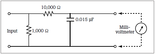
The figure above represents the impendence of a patient test load. Leakage current measuring devices use this impedance circuit for measurements.
A new IEC standard, IEC 62353, is used for medical device testing in hospitals. IEC 62353 was developed because IEC 60601.1 is a type-testing standard with no risk management criteria and is impractical for testing in the hospital environment.
IEC 62353 tests are performed on equipment prior to use on patients, during schedule periodic testing, and after repair. Thus, this standard is for field (hospital) testing and does not address equipment design. In Annex E of the document, the manufacturer is requested to provide information on testing interval and procedure based on risk, typical usage, and device history. The minimum testing requirement for life support and other critical equipment is every 24 months.
Global harmonization of standards has led to the development of worldwide standards. Equipment in the regions listed below must be certified to the IEC60601-1 standard or the device cannot be sold in that country.
| IEC60601 | AAMI/NFPA 99 |
| Protective Earth Resistance | Ground Wire Resistance |
| Earth Leakage Current | Ground Wire Leakage Current |
| Touch or Enclosure Leakage Current | Chassis Leakage Current |
| Patient Leakage Current | Lead to Ground Leakage Current |
| Patient Auxiliary Leakage Current | Lead to Lead Leakage Current |
| Mains on Applied Part (MAP) Leakage Current | Isolation Leakage Current |
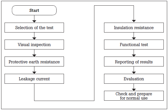
Testing requirements and sequence according to IEC 62353 Annex C are shown below. Only measurement equipment that meets IEC 61010-1 should be used. The sequence outlined in the figure below should be followed. For example, protective earth resistance should be measured prior to leakage current measurements.
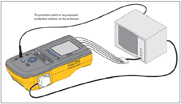
General connections to an electrical safety analyzer (ESA) are shown in Figure 5-5. Consult the operational manual for specifics for your electrical safety analyzer. Documentation requirements for IEC 62353 include:
Computerized record-keeping systems are greatly preferred for data storage, search, review, and analysis. Note the device fields must be standardized.
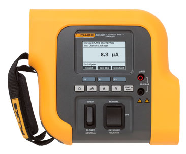
The ESA609 integrates all functions needed to test medical devices when patient lead testing is not required, including:
Versatile to global electrical safety standards of choice, the ESA609 tests to ANSI/AAMI ES1, NFPA-99, and parts of IEC62353 and IEC60601-1. To learn more about the ESA609 Electrical Safety Analyzer or any other Fluke Biomedical analyzer, click here or visit www.flukebiomedical.com
Introduction to Introduction to Electrical Safety—Part II will cover:
Fluke Biomedical
6045 Cochran Road
Cleveland, OH 44139-3303 U.S.A.
For more information, contact us at:
(800) 850-4608 or Fax (440) 349-2307
Email: sales@flukebiomedical.com
Web access: www.flukebiomedical.com
