
One of your principal duties as a medical equipment technician is to assure the safety of the many devices for which you are responsible. However, the standards for the design of this equipment are continually evolving, and it is important for you, the technician, to be current with the standards and how to test to them. This paper will give an overview of the intrinsic hazards of medical devices, electrical safety standards, and describe a testing procedure for the most commonly used standard in North America.
In Healthcare Technology Management (HTM), any discussion about electrical safety must begin with Ralph Nader’s famous article in March of 1971, in which he alleged, ”…about 1,200 people a year are electrocuted” in hospitals due to poor equipment design and inadequate or incompetent maintenance of that equipment. Nader’s numbers may have been inflated, but his article set in motion a great deal of discussion about the safe design and maintenance of medical technology. This was a classic case of technology advancing much faster than the standards for its care. In the early 1970s, medical technology was beginning to evolve exponentially, but the standards for safe design and routine safety verification lagged behind the need. In the four decades since then, medical devices that diagnose and treat disease, or assist with treatment have advanced dramatically in complexity and number, and standards have been written and periodically amended to assure the equipment poses minimal risk both to the patient and the clinician. Patient safety should be paramount in the mind of the HTM technician. Our customers, the patients, are a vulnerable population who trust us to provide safe equipment for their care; our colleagues—physicians, nurses, and technologists—trust us to assure that the equipment is safe, as well as functional.
Electrical safety is all about assuring that current flows only where it is designed to flow, and about minimizing the flow of unintended current. Unintended current is parasitic otherwise
known as “leakage” current, that travels across the impedances that are inherent in any device. It cannot be totally eliminated. If there is sufficient leakage current, it poses the risk of shock, especially for patients whose clinical defenses are compromised.
A shock hazard exists if:
A few examples:
Any of these, and countless other scenarios, can create excessive leakage current.
Over the past four decades, a number of standards for the electrical safety of medical devices have been written. These documents are based on the best current design principles. Since components and design practices are always changing, the standards are revised periodically, typically every five years.
The benchmark standard worldwide is IEC 60601-1: Medical Electrical Equipment – General Requirements for Safety and Essential Performance, originally published in 1977 as IEC 601 by The International Electrotechnical Commission in Geneva. Primarily intended to be used for the design and production of medical devices as well as used by end-user facilities for periodic safety testing, it is currently in its third edition. Over the past thirty years it has been adopted, with slight variations, by a number of national agencies:
Standards have been published that parallel the intent of 60601-1, but are primarily for periodic safety verification by the clinical user facility, without the more rigorous “type testing” and production testing required of manufacturers. These include:
In May of 2007, the IEC published IEC 62353: Medical Electrical Equipment—Recurrent Test and Test After Repair, to harmonize with those standards intended for periodic in-house testing. Its tests reflect the higher level of protection designed into medical devices in the recent decade, and include earth bond testing, insulation testing, and three different ways to measure leakage current, depending on the type of device.
Additionally, in 2004 the IEC published its standard 61010-1: Safety Requirements for Electrical Equipment for Measurement, Control, and Laboratory Use. It includes devices used in the clinical laboratory, and so is pertinent to the HTM technician. If your routine maintenance includes laboratory equipment, you will need an analyzer that tests to this standard.
Ultimately, it is up to each facility’s Clinical Engineering department to decide which testing standard it will apply, with deference to any governmental authority. (e.g. In the U.S., some state governments have adopted NFPA-99 as code in their jurisdiction, requiring its use by law.) Whatever standard is used, test results for each device must be recorded and retained.
Comparing the major standards is made more challenging by differences in English language terminology between the North American and the European documents. The following terms are used in the text and associated schematics:
| International: | North American: |
| L1 | the ‘Hot’ or energized line |
| L2 | the Neutral line |
| Earth | Ground |
| Enclosure or Case | Chassis |
| Mains Voltage | Line voltage (the facility wiring voltage) |
| Protective Earth | Ground Wire |
Any conductive components that are intended to contact the patient in normal use. Examples: connectors for ECG or EEG electrodes, defibrillator pad connectors or paddles, active or return ESU electrodes.
Current that flows in the Earth wire of a protectively earthed device.
Current that flows to earth from any exposed conductive part of the enclosure other than through the protective earth wire.
Protection includes a Protective Earth wire.
Class I protection, plus a second layer of enclosure insulation (‘Double Insulated’)
Note that any device that can be connected to the mains (even if battery driven) is classified as a Class I or Class II device. Some devices have no mains connection, are typically internally powered by a battery, and use “safety extra low voltages” (less than 25Vac or 60Vdc).
Current that flows to earth through a patient connected to an applied part or parts.
Current that flows between applied parts which serves no design purpose.
Current that flows to earth through the applied parts (connected as one) when momentarily connected to the mains voltage.
A condition in which a normal connection (Earth or L2) is open.
Complete protection against shock. Primarily external applications.
Applied parts to the patient’s skin; input circuits are isolated.
Applied parts including direct cardiac contact. >70MΩ from mains to applied parts.
Tests shown here apply to both the NFPA-99 and AAMI ES-1 standards, for line-powered devices that are used in the patient care vicinity, and portable (i.e. not ‘fixed’ devices which are physically secured to the building). North American terminology will be used.
The chart below is a condensed version of Table 1 of the ANSI/AAMI standard ES-1. “Fixed” equipment is permanently installed with an integrated ground (only removable with tools). In the Earth (Ground) Risk Current group, “Other” refers to devices that have no grounded accessible parts and no means of being grounded (this includes mobile X-ray equipment).
By separating-out a few exceptions, the table can be summarized for portable devices as follows:
Normal condition: 100 μA
Single Fault Condition: 300 μA
except No Patient Contact devices: 500 μA)
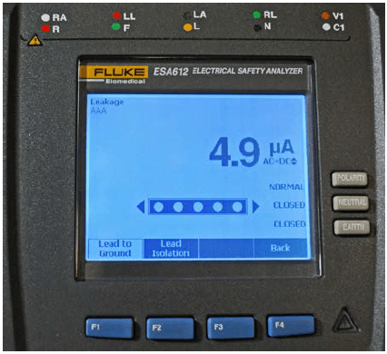
Normal condition: 10 μA
Single Fault Condition:
Isolated devices: 50μA
Non-Isolated devices: 100 μA
| Consolidation of ANSI/AAMI ES-1, Table 1 | ||||||||
| Enclosure Risk Current, μA | ||||||||
| Isolated | Non-Isolated | Likely Pt Contact | No Pt Contact | |||||
| Portable | Fixed | Portable | Fixed | Portable | Fixed | Portable | Fixed | |
| Normal | 100 | 100 | 100 | 100 | 100 | 100 | 100 | 100 |
| Single Fault | 300 | 5000 | 300 | 5000 | 300 | 5000 | 500 | 5000 |
| Patient Applied Part Current, μA | ||||||||
| Isolated | Non-Isolated | Patient Isolated | ||||||
| Normal | 10 | 10 | n/a | |||||
| Single Fault | 1000 | 5000 | 1000 | |||||
| Earth (Ground) Risk Current, μA | ||||||||
| Coded | Other | Fixed | ||||||
| Normal | 500 | 2500 | 5000 | |||||
| Single Fault | 1000 | 5000 | 1000 | |||||
Normal condition: 500 μA
Single Fault condition: 1000 μA
Earth (Ground) Risk Current for Other Devices:
Normal condition: 2500 μA
Single Fault condition: 5000 μA
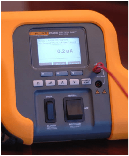
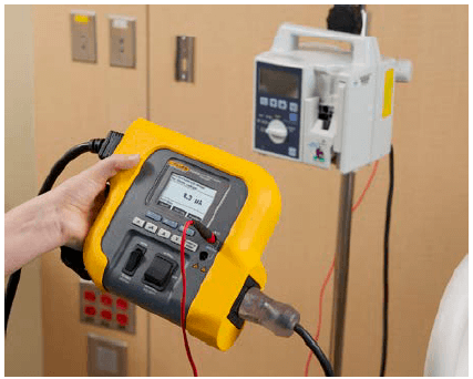
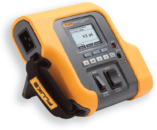
The Electrical Safety Analyzer The choice of safety analyzer is driven primarily by the testing standard being used, and most analyzers are designed to test to a variety of standards. Regardless of which standard is used, the safety tests they have in common are:
Additionally, some standards require all testing at 110 % of line voltage, the Insulation Resistance, etc. The standard will determine those capabilities required of the analyzer. If the device under test has no applied parts, a more basic analyzer will do. Further considerations are the capability for data storage, automated test sequencing, and patient simulations.
Before testing, it is essential that the user understands the analyzer. Incompetent use of an analyzer can waste time, create erroneous test results, potentially damage the device under test, or even put the user at risk of shock. Additionally, many users do not take advantage of useful supplemental features of their analyzers, such as point-to-point tests or performance waveforms. Before testing, read the user manual, and practice testing on a functioning device.
Some medical devices (especially portable devices) suffer a great deal of abuse between inspections, and clinical personnel may not always properly clean them or report damage, which could result in a safety hazard. Inspect the device for dents, cracks, or misalignments of enclosure sections. It is part of the inspection to take the time to clean the unit of the dirt, dust and dried liquid. Inspect the power cord,
especially the plug. Inspect the patient interface components: cables, tubing, pads, cuffs, etc. Anything that is damaged or beyond cleaning for reasonably good appearance should be replaced.
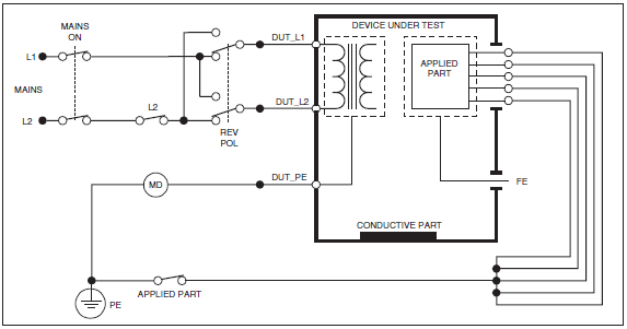
Select the standard that you will be using, then verify if the device to be tested is used in the patient care vicinity (defined in IEC 60601), and whether it is a Class I (line- powered) or Class II (double insulated) device. For some testing standards, you will need to know whether the device has Type B, Type BF, or Type CF isolation. For those tests which include reversing the polarity of the mains, the analyzer may offer a choice of time delays as a safeguard against damaging the unit under test.
Measure the voltage from Hot to Neutral, from Neutral to Ground, and from Hot to Ground. The voltage from Hot to Neutral and from Hot to Ground should be within +/- 10% of nominal. On 120v wiring, there should be no more or less than 3.6v from Neutral to Ground.
Several of the standards specify that the Ground Wire resistance should be measured first, before testing for any of the leakage currents. NFPA-99 and AAMI ES-1 set the maximum acceptable resistance at 0.50 Ω. IEC 60601-1 sets lower limits. Since the values being measured here are very low, the resistance of the testing leads must first be zeroed, or nulled, before making a measurement.
It is a good practice (in fact specified in most standards) to stress the power cord at both connector ends while testing, in order to detect any incompetency of the ground wire continuity. The slightest amount of oxidation on the blades of the plug will also impact the resistance reading.
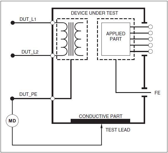
The analyzer is configured to measure the current in the Ground Wire.
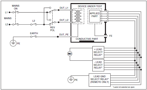
The analyzer measures current from the device’s enclosure; usually, the “ground pin” is the best option. In the absence of a ground pin, you may connect to any conductive feature likely to be contacted by the patient or user, and which is continuous with the enclosure.
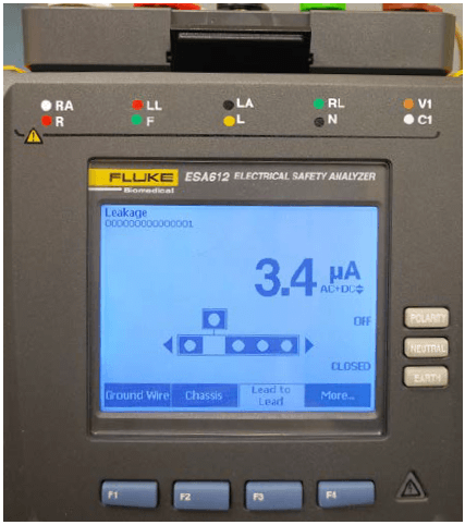
This measures the current between any and all conductive components which necessarily come in contact with the patient in normal use. Measurements are taken from each applied part, and from all applied parts connected together, Auxiliary (“Lead to Lead”) Leakage Current:
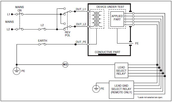
The analyzer is configured to determine the current between any two applied parts or any combination of applied part groups, user-selectable on the analyzer.
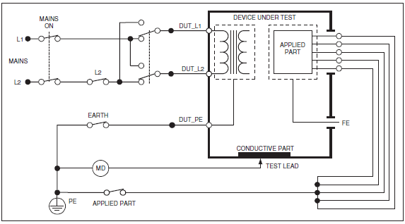
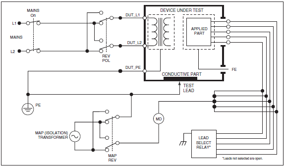
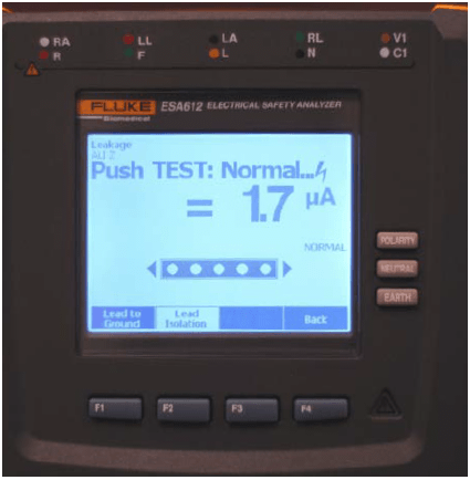
In order to verify that the isolation of the applied parts is competent, this test exposes the applied parts, connected together, to the mains voltage created by an isolation transformer within the analyzer.
As members of the Clinical Engineering team, our goal is to assure the safety and reliability of the technology that is used for patient care. Electrical safety standards will continue to evolve and harmonize in the future, and an essential function of the technician is to be current with the standards, and apply them consistently.
To learn more about electrical safety or any of the analyzers discussed in this paper, please visit www.flukebiomedical.com
Dennis J. McMahon, CBET-R, is a medical equipment technician with almost forty years of experience. After earning a degree in Chemistry in the late ‘60s, he worked as an anesthesia technician until 1977. He certified as a biomedical equipment technician in 1983, and worked for Virginia Mason Medical Center until 2011. He also volunteered in seven missions with Operation Smile between 2002 and 2011. Dennis has instructed in Healthcare Technology Management at North Seattle College since 2002, and has written a number of papers in the medical literature, and for Fluke Biomedical. He currently serves as the Education Chair for the Washington State Biomedical Association (WSBA).
Fluke Biomedical
6045 Cochran Road
Cleveland, OH 44139-3303 U.S.A.
For more information, contact us at:
(800) 850-4608 or Fax (440) 349-2307
Email: sales@flukebiomedical.com
Web access: www.flukebiomedical.com
 Protecting your privacy is important to us. We will never sell, rent or disclose any of your personal information, including your email address, to any third party without your prior or explicit consent.